

Out Kickstarter campaign is now over but you can still pre-order your Protractor on Tindie.

The Protractor is a proximity sensor that tells you the angle to nearby objects and open pathways. A lot of sensors can tell the distance to an object, but determining the angle is much harder. Knowing the angle between your robot and nearby objects and pathways is useful for robotic applications such as Mini Sumo, Bulldozer, Object Collection, Obstacle Avoidance, Maze Solving, and many more. For tasks like these, the Protractor sensor tells you exactly what you need to know. With a 180 degree field of view, the Protractor can tell the angle to multiple objects up to 30cm (12 inches) away.

The Protractor is a proximity sensor that tells you the angle to nearby objects and open pathways. A lot of sensors can tell the distance to an object, but determining the angle is much harder. Knowing the angle between your robot and nearby objects and pathways is useful for robotic applications such as Mini Sumo, Bulldozer, Object Collection, Obstacle Avoidance, Maze Solving, and many more. For tasks like these, the Protractor sensor tells you exactly what you need to know. With a 180 degree field of view, the Protractor can tell the angle to multiple objects up to 30cm (12 inches) away.

The Protractor works well with robots from about 10 to 25 cm (4 to 10 inches) in size. The Protractor can communicate with Arduino, Raspberry Pi, and most other popular microcontrollers using I2C or Serial communication.
How it Works
The Protractor is an active infrared (IR) sensor. An array of IR LEDs emits light in different directions, and the sensor measures how much light bounces off nearby objects from each direction. A special algorithm processes the signals and calculates the angles to the objects and open paths.

The Protractor will output the angles whenever requested by a host microcontroller over I2C or Serial. We have written a Library for the Arduino with examples showing how to use basic and advanced features of the Protractor. The Library can be downloaded from our Github page: http://github.com/robogao/Protractor.
The Protractor uses LEDs to provide user-friendly feedback and help with troubleshooting. A green LED indicates when the Protractor has received a command while two blue LEDs indicate what the Protractor sees. The Blue LEDs can be set to indicate the angle to the most visible object or an open path.

Although the Protractor is not a distance measuring sensor, it can provide a relative measurement of the intensity of reflected light. If it is known in advance that several objects reflect the same amount of light, then the intensity of reflected light can be used to indicate which object is closer.
Technical Specs
Performance Characteristics
Parameter
|
Symbol
|
Min
|
Max
|
Units
|
Operating Voltage
|
Vin
|
6.01
|
14.0
|
V
|
Average Current Draw
|
Iin_ave
|
10
|
85
|
mA
|
Peak Current Draw
|
Iin_peak
|
860
|
mA
| |
Emission Wavelength
|
λ
|
820
|
880
|
nm
|
Level Shifter Voltage Reference
|
VCC
|
2.7
|
5.5
|
V
|
Communication Pin Voltage
|
SDA, SCL, TX, RX
|
2.7
|
5.5
|
V
|
Refresh Rate
|
Adjustable, See Notes
|
67
|
Hz
| |
Startup Time
|
500
|
ms
|
1Can be operated at 5V with modification.
The graph below shows the typical performance of the Protractor’s ability to measure angles.

Target Object = 3” long piece of 3” size white SCH40 PVC pipe
Test Conditions: Ambient Light = 100 lux, Vin = 12V
Field of View
The Protractor is designed to see a full 180 field of view in the plane of the circuit board. To maximize sensing distance, objects should be located in the same plane as the board. An object located up to about 25 degrees off the horizontal plane may be visible, but the effective sensing distance will be reduced. In general, objects should be within 10 degrees of the plane of the Protractor.
Sensing Distance
The further an object is away from the Protractor, the more difficult it is to see. Because the sensor relies on the reflection of IR light, objects with large and bright surfaces are ideal. Objects with small and dark surfaces will have reduced sensing range or may not be sensed at all.
When used indoors away from direct sunlight, the Protractor can generally see a white wall up to 14-16 inches away. A piece of 3” white PVC pipe can typically be seen 12” away, and 1” white PVC pipe can typically be seen 8” away.
The Protractor is suited for use indoors with lighting conditions of 1000 lux or less. When exposed to direct sunlight the sensors become saturated and unable to sense reflections off nearby objects. When used indoors, the performance can be maximized by keeping it away from large windows, open flames or other sources of IR light. The sensing distance will generally be greater under LED or Fluorescent lighting vs incandescent.
Power Source
The Protractor operates on 6 to 14V power source and can draw up to 600ma peak current. The Protractor can be connected directly to a 6 to 10 cell NiMH battery or a 2S to 3S LiPo battery. For stationary applications, a good quality power supply capable of supplying 1A or more should be used. If the Protractor senses that its input voltage is too low, the blue LEDs will flash alternately and the Protractor will suspend sensing until the input voltage is in the normal operating range.
It is possible to modify the Protractor so it can operate from a 5V power source. To do this, jumper SJ2 should be shorted with a ball of solder. This will connect the Protractor’s 5V logic circuitry directly to Vin. Vin must not exceed 5.5V when SJ2 is shorted otherwise the Protractor will be permanently damaged. When operating the Protractor from a 5V source, it is recommended to add extra capacitance to the board. See below for details on reducing peak current.
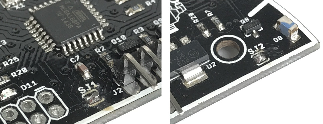
One additional modification of the Protractor will allow the sensor to communicate with a 5V microcontroller without the need to make a connection to VCC. If solder jumper SJ1 is shorted, then VCC will be connected to the sensor’s internal 5V supply, and the communication signals (SDA, SCL, TX and RX) will operate from 0V to 5V. This modification should only be done if the Protractor is connected to a microcontroller that is 5V tolerant, otherwise damage to the microcontroller may occur.
Level Shifting
The Protractor has built in level shifting circuitry for SDA, SCL, TX and RX communication lines for use with 5V and 3.3V microcontrollers.
Reducing Peak Current
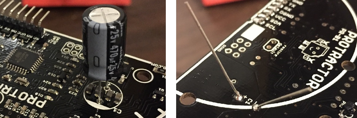
The peak current draw of the Protractor can be reduced by soldering additional capacitance to the board. Location C1 shown in the picture below is the best place to add capacitance. A quality capacitor of 470 μf and equivalent series resistance (ESR) less than 0.2 ohms can reduce peak current below 0.15A. Double check the polarity is correct before soldering a capacitor to the board.
Scan Time
The Protractor can be configured to scan continuously or only when requested. The default is continuous scanning mode and a full 180° scan takes about 15 milliseconds to complete. For best performance, it is recommended to wait 15 milliseconds or more between each request for data from the Protractor.
The scan time can be changed by using the appropriate function call. The peak current draw will remain the same, but the average current draw can be reduced to 11ma. The time for a full scan can be changed from 15 milliseconds up to 32 seconds. See the Change_Scan_Time example in the Protractor Library for details.

Setting the scan time to 0 will stop continuous scanning. A single 180° scan will be performed each time data is requested. There will be approximately 15 millisecond delay between the time when data is requested and when the Protractor replies with the angles. This mode offers the greatest potential for power savings and can be used to disable the sensor during periods of non-use.
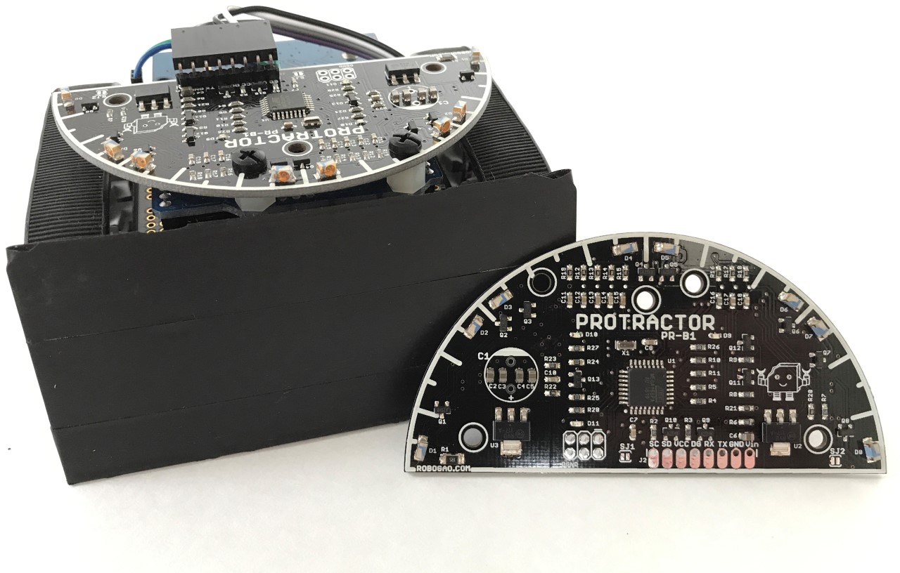
Dimensions
The Protractor is a semicircular circuit board that is 3.5 inches in diameter. The thickness is 0.25 inch not including headers or extra capacitance. The board has 5 mounting holes that accept 4-40 or 3mm machine screws for mounting. Nylon or other plastic screws and standoffs are recommended for mounting.

The Protractor should be mounted in a location where it has a clear and unobstructed view of the surroundings. Before permanently mounting the Protractor to your project, test with the sensor in place to determine if it sees any part of your robot or other nuisance objects that could interfere with the accuracy of the angle measurements. If it is not possible not move all interfering objects out of the Protractors field of view, try painting the object black or covering it with black electrical tape to minimize interference.
Looking to protect your Protractor? A customizable case designed for the Protractor can be downloaded from Thingiverse which you can print from home. This design can be made from ABS or PLA, just as long as its black or other very dark color to minimize light reflections.
If you don't have a 3D printer, you can order a case from our Shapeways store. Not only will the case keep your Protractor safe, it also helps shield the sensor from ambient light to maximize the sensing range. This case is made from the Black Strong and Flexible nylon material which has a coarse finish perfect for minimizing reflections. To help you save money, the top and bottom halves of the case are printed as a single part with small tabs connecting the two halves. They can be separated by lightly scoring the tabs with a knife.
ConnectionsLooking to protect your Protractor? A customizable case designed for the Protractor can be downloaded from Thingiverse which you can print from home. This design can be made from ABS or PLA, just as long as its black or other very dark color to minimize light reflections.
If you don't have a 3D printer, you can order a case from our Shapeways store. Not only will the case keep your Protractor safe, it also helps shield the sensor from ambient light to maximize the sensing range. This case is made from the Black Strong and Flexible nylon material which has a coarse finish perfect for minimizing reflections. To help you save money, the top and bottom halves of the case are printed as a single part with small tabs connecting the two halves. They can be separated by lightly scoring the tabs with a knife.
Protractor Connections
Pin Name
|
Description
|
Vin
|
Input Voltage
|
GND
|
Ground
|
TX
|
Serial Transmit
|
RX
|
Serial Receive
|
DGND
|
Digital Ground
|
VCC
|
Level Shifter Supply Voltage
|
SDA
|
I2C Data
|
SCL
|
I2C Clock
|
Power connections to Vin and GND should be connected as close as possible to the power source. For reliable operation in your project, it is recommended to bypass the microcontroller’s PCB and connect the Protractor’s Vin and GND pins directly to the output of the power supply.


Power Connections
VCC on the Protractor should be connected to the voltage source of your microcontroller. VCC should be connected to the 5V pin for 5V microcontrollers such as Arduino Uno, Nano or Mega. VCC should be connected to the 3.3V pin for 3.3V microcontrollers such as Arduino Due, Zero or Raspberry Pi. In addition, DGND (digital ground) on the Protractor should be connected to GND on the microcontroller.
Communication can be handled using an I2C bus or Serial UART port. If your Arduino microcontroller only has a single hardware serial port, such as the Uno or Nano, it is recommended to use either I2C or a Software Serial connection. The one hardware serial port should be left open for debugging your project.
I2C Communication
Protractor Pin
|
Arduino Uno
|
Arduino Mega
|
Arduino Due
|
Raspberry Pi
|
SDA
|
SDA/A4
|
SDA/20
|
SDA, D20
|
SDA
|
SCL
|
SCL/A5
|
SCL/21
|
SCL, D21
|
SCL
|
Serial Communication
Protractor Pin
|
Arduino Uno
|
Arduino Mega
|
Arduino Due
|
Raspberry Pi
|
TX
|
RX: SW Serial1
|
RX1: D19,D17,D15, SW Serial
|
RX / RxD
| |
RX
|
TX: SW Serial1
|
TX1: D18,D16,D14, SW Serial
|
TX / TxD
| |
1Arduino Mega and Due have multiple Hardware Serial Ports.
The Protractor has built in level shifting circuitry for SDA, SCL, TX and RX communication lines which can be connected directly to the pins of a 3.3V or 5V microcontroller.
Software Library
Getting started with the Protractor and an Arduino is easy. A Protractor library with lots of examples is available at: https://github.com/robogao/Protractor
To install the library to use with the Arduino IDE, follow the steps at https://www.arduino.cc/en/Guide/Libraries
Once the library is installed, hookup the Protractor to your Arduino according to the I2C or Serial connections shown above. In the Arduino IDE, go to File -> Examples -> Protractor and try out the Basic example that matches your wiring.
For in-depth descriptions of the available functions, check out the “readme” file that is included with the Protractor library.
Basic Functions
- Number of objects in view
- Number of open paths in view
- Angle to each object in view
- Angle to each open path
- Visibility of each object
- Visibility of each open path
Settings
- Changing the scan time
- Changing the LEDs behavior
- Changing the serial baud rate
- Changing the I2C address
Restoring Default Configuration
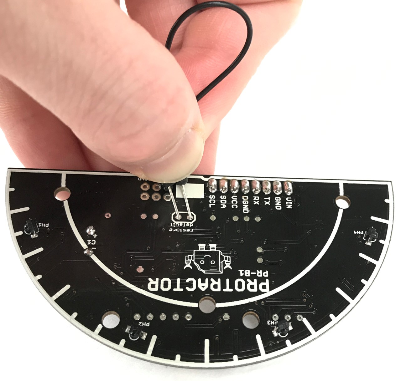
Changes to the serial baud rate and I2C address are remembered after the Protractor is powered off. If at any time you’re not certain about the Protractor’s configuration, the default settings can be restored by connecting the two “restore default” pads on the underside of the Protractor during power up. This will set the I2C address back to 69 and the serial baud rate back to 9600.
Connecting to the Pololu Zumo Shield
The Protractor works great with the Pololu Corporation’s Zumo Shield mini sumo robot for Arduino. Two of the Protractor’s mounting holes are in the perfect location to attach the Protractor to the back side of an Arduino Uno or Leonardo using 4-40 or M3 screws and ¼” or 6mm standoffs or spacers.
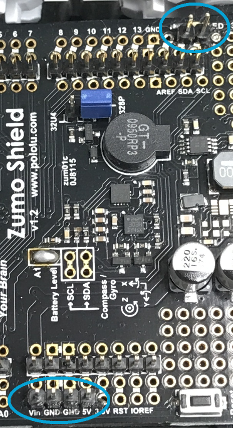
The Zumo Shield has convenient breakouts for all of the Arduino pins. Its best to connect the Protractor to the I2C bus along with the accelerometer and gyro so as to not consume any additional pins. Connecting to SDA and SCL can be done by soldering wires directly to the shield or by installing a header on the breakout pins as shown to the right. Power can be found on the opposite side where Vin, GND, GND, and 5V are all in a row. A 4 pin header can be installed here or wires soldered directly to the shield. The Vin supply on the Zumo Shield can handle the peak current demand of the Protractor while the 5V supply should only be connected to the Protractor’s VCC pin.
If installing headers, it is recommended to make connections on the breakout rows closest to the edges of the shield. This way the headers and connector won’t interfere with the edge of the Arduino when placed on top. Hookup wires 10cm long with male connectors work well for connecting headers on the Protractor to the Zumo Shield.
The Protractor Library includes an example sketch ZumoProtractor.ino to get your Zumo robot up and running with the Protractor in no time.

If you’re looking for a challenge, try some of these ideas:
- Changing the example code to use a PID loop to track the opponent
- Make precise turns using a nearby object as a reference
- Drive around obstacles or navigate a walled maze without bumping into anything
- Drive along a wall maintaining a consistent distance
Zumo is a product of the Pololu Corporation and is not affiliated with Robogao LLC.
Useful Tips
As a sensor, the Protractor is typically mounted on the front of your project and is subject to getting banged around. Take care to protect your Protractor from injury. Exposure to cabinets are a leading cause of Protractor injuries so be sure to mount it at an altitude that will keep it safe from low overhangs.
